Fecha actual Mar Mar 19, 2024 1:13 am


Todos los horarios son UTC - 4 horas


Nuevo tema Responder al tema
Autor Mensaje
 Asunto: HOW TO 2012+: Gauge Pod Installation
NotaPublicado: Jue Ago 29, 2019 9:10 pm 
Administrador
Administrador
Avatar de Usuario
Registrado: Vie Nov 26, 2004 5:27 pm
Mensajes: 3874
Ubicación: Guánica
País: Puerto Rico (pr)
Género: Hombre
Facebook: Facebook
New Beetle:GLX 1.8T 2000

From VWvortex

Hi all.

I knew before I bought a Beetle that I was going to want to do this DIY, and I could not find all the information I needed on the internet, so I am adding my experience to this thread. I actually purchased the harness from Kufatec and a gauge package off eBay before I even bought the car, a 2016 Beetle 1.8t. I could find no conclusive information that the additional instruments would even work in a Beetle 1.8 turbo, but I sawed up the dashboard on a vehicle with less than 200 miles on it, so I concur with the others that this project is not for the faint-hearted. I am happy to report that it works! I can't imagine the embarrassment and humiliation (not to mention the cost) of taking my vehicle back to the dealership for a new dashboard if this had not turned out well.

Here is a list of things to have before starting the project:

1. Patience!
2. A steady hand for using a Dremel, or a buddy to help who is crafty and good with tools. I recruited a friend.
3. A helper. In this case I played the role of helper, because I would have screwed up the cutting of the holes.
4. A gauge package, including base. I used part number 5C5-919-527-C from a vehicle with 5500km on it, found on eBay.
5. The Kufatec Harness, part number 40206.
6. Tesa Wire Loom Harness Tape, part number 51608 or similar. This came from Amazon.
7. Trim/Moulding Tool Kit. I got this at ECS Tuning, ECS part number ES#517779.
8. De-burring tool (General Tools model 482).

Other general purpose tools included Torx Screwdrivers, Wire Cutters, Heat Gun, Screwdrivers (jewelers and regular size), Soldering Iron, Heat-Shrink Tubing, 12 volt circuit/continuity tester, a shop vacuum, a sharp razor knife, and a Dremel rotary tool with several bits.

Apparently optional is Ross-Tech VCDS interface and software, but I recommend this or you will end up with error codes in your CAN Gateway.

A note on selecting your gauge cluster on eBay or wherever you get it: There are at least four different model numbers for the additional instrument cluster and I don't have much idea on what the differences are. Some of the instruments display English measurements and some are Metric, so that may be the difference but I know the 5C5-929-527-F and 5C5-929-527C both display in English units, so I don't know what to tell you. Make sure you are buying an instrument cluster that displays correctly for your region. I wanted my oil temperature in Fahrenheit and my Turbo Boost in PSI. You will find these instrument clusters on eBay listed as "Additional Instruments", "Auxiliary Meters", or a good search term might be 5C5-919-527. Many of the ones on eBay don't include the base or the housing and you will need these also, so maybe get the missing pieces (if any) from a dealership.

These are the three pieces individually, the one I got on eBay came from a salvage yard and included the three pieces, already assembled.

Imagen

So I asked my buddy if he would drill a bunch of holes in the dashboard of my brand new car, and he did not want ANY part of it at first, but he eventually relented, so this is what we did:

After removing the stereo head unit, air conditioning vents and rubber pad in the center of the dash, my friend marked some of the mounting tabs on the bottom side of the gauge package with paint and we carefully set it on the dashboard to mark where to start drilling holes. The first holes we drilled were where the gauge package hangs down the lowest, i.e. the first part of it to contact the dashboard when you set it where it is going to go. Then we would mark the gauges with more paint and test fit them. The next holes we drilled were wherever the unit was touching the dashboard again, etc. The key to doing it this way is to really take your time, drill small holes, test fit the gauges, enlarge the holes, test fit the gauges, enlarge the holes some more. Enlarge the holes by small amounts each pass, and de-burr and clean up the holes each time you enlarge them. Hugely useful was to have somebody hold a shop-vac nearby and suck up the shavings as the holes are drilled. Millions of tiny black pieces will go everyplace, and the best policy for sure is to suck them up as they are created.

My friend asked me one more time if I really wanted him to drill the dashboard of my new car and I said "It's only $25,000 down the toilet if we screw this up!"
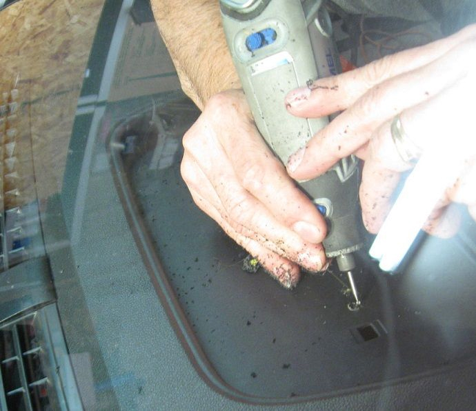
While we laughed like idiots, in disbelief at what we were doing, the drilling began. Here we are starting the first hole without the vacuum cleaner, and what a mess!

Imagen

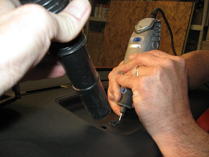
Obviously this way is much better.

Imagen

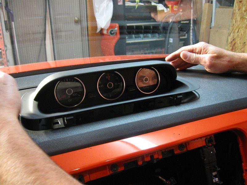
Here is the first test fit, to ascertain where to drill the next holes or where to widen a hole.

Imagen

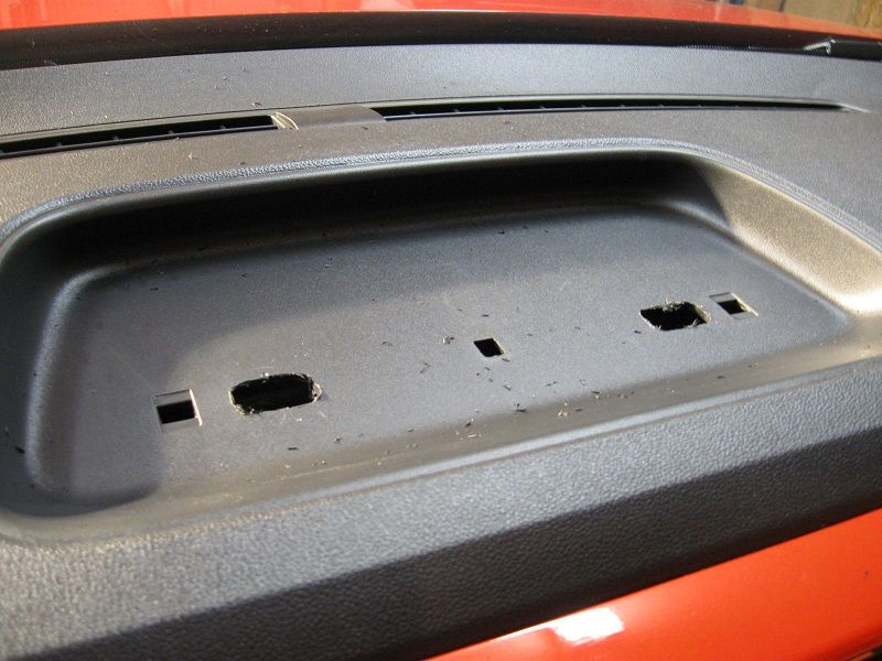
This shows the only holes we had drilled by that time.

Imagen

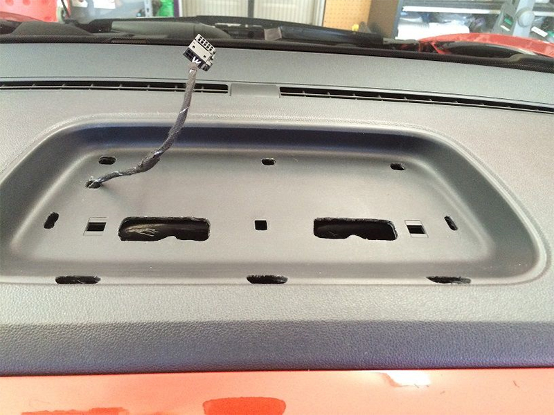
Here is what we eventually wound up with... note an extra hole drilled for the Kufatec harness, which we fed down through this hole.

Imagen

Don't be afraid to enlarge your holes to the left or right, forward or back in very small increments to make sure the unit is centered and looks good. At one point, my buddy and I noticed that the gauges appeared to be sitting a tiny bit towards the left side of the recess (I'm talking a millimeter, or 1/100 of an inch or so), and we widened most of the holes ever so slightly to the right, wondering if we were enlarging the holes too much. Happily, the unit now sat centered, and it fit better too!

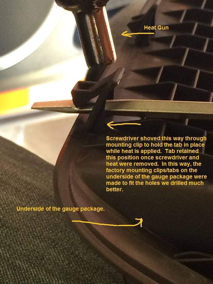
Once we were done and the unit fit squarely, I was dismayed to find that the clips on the underside of the unit really didn't grip my dashboard too well... it was easy to pry the thing back out by hand. I wondered if this would cause it to rattle, and I suggested we insulate it against rattles by placing some cloth tape underneath it. My friend had a much better idea... use a heat gun to soften the plastic clips and bend them such that they would lock in place much tighter in our non-factory spec holes.
Here is how he did that:

Imagen

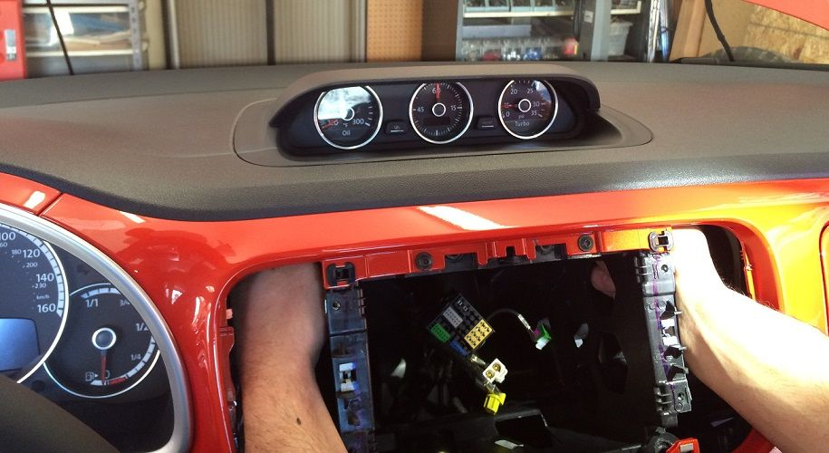
In the end, the unit locked in place so tightly that we were not able to remove it, even using the plastic trim tools from ECS Tuning! I can report that it does not rattle at all. Here it's in place and he is reaching for the wire harness.

Imagen

The "instructions" that come with the Kufatec harness are shamefully inadequate, mostly consisting of generic warnings about safety. The sixth page has the only useful information. Disconnect the vehicle battery and connect as follows:

Pin 1 = Permanent Positive (cable imprint = rot > red)
Pin 3 = Ignition Positive (cable imprint = Schwarz > black)
Pin 6 = Ground Connection (cable imprint = Masse)
Pin 7 = CAN High (Engine - CAN-BUS, orange/black)
Pin 8 = CAN Low (Engine - CAN-BUS, orange/brown)


Imagen

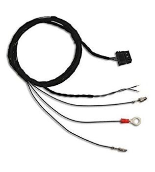
Unrolled, the Kufatec harness is an inverted Y shape. The connection to the additional gauges is at the top, one leg of the wye is the proper length to go to the fuse block, and the other leg is the proper length to go behind the standard instrument cluster (speedometer), where you can find the CAN High and CAN Low wires to tie into.

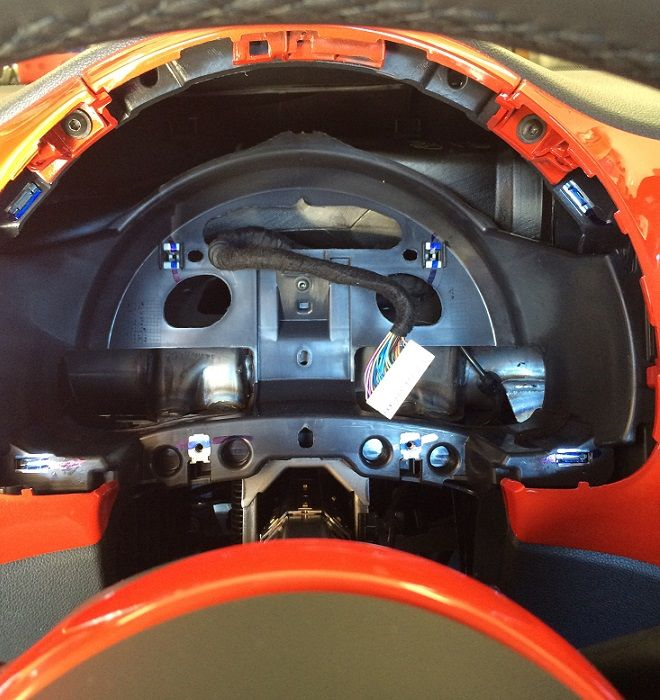
The trim around the instrument cluster comes out with the top panel of the steering column as one bizarre, unwieldy unit. These pieces are connected together, so be careful when you remove them. The closest part of the top panel of the steering column pops up and toward you as you sit in the driver seat. Then you can use a trim tool to remove the trim from around the instrument cluster. Once that's off, it's only four screws holding the instrument cluster in... be very careful when you remove it, you don't want to scratch the delicate plastic face of your speedometer and instruments.

I bought a one-year subscription to Chiltondiy.com for this project, to have access to diagrams of the instrument cluster pieces and some idea how they come apart and fit back together, but if you are careful and stop and Google anything you have trouble with, you might be okay without that.

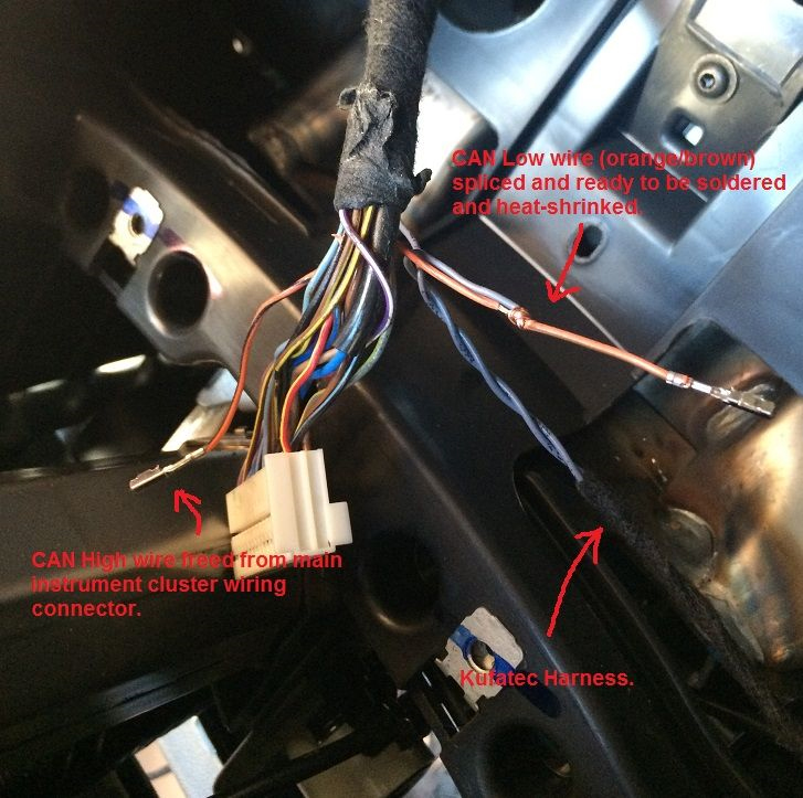
Now here is a picture of what you are interested in... the wiring harness behind the main instrument cluster. In this harness are the CAN High and CAN Low wires for the Engine CAN-BUS.

Imagen

You need to very carefully expose some of the wires above the connector so that you can patch the Kufatec harness to the CAN High (orange/black) and CAN Low (orange/brown) wires in this wiring bundle. We used jeweler's screwdrivers to release the CAN BUS wires from the wiring connector to make them easier to work on, but you could probably skip this if you are careful.

Imagen

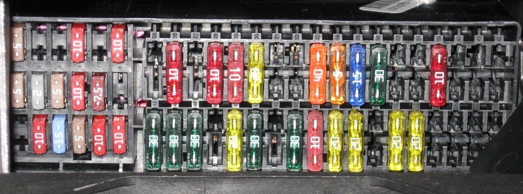
Now for the fuse block... I found the fuse block behind the left-knee cubby to be impossible to remove without first removing all the screws from the lower dashboard panel at the driver's knees. Mostly this consisted of just removing a few screws, and then the panel would shift sufficiently that I was able to remove the fuse block for easier access to the back side of it. My friend used the circuit tester to find which bus in the fuse block was permanent positive (always hot), and which was ignition positive (hot when the ignition is switched on). Attaching the Kufatec harness to this was easy, as the harness has connectors which just pop into the fuse block. Pick two available slots (we used numbers 29 and 51) and push the wiring connectors right in. We then installed 10-amp fuses in the sockets we connected to in the fuse block. I can't recall whether 29 was permanent positive and 51 is ignition positive or vice versa.

Imagen

Now button it all back up and get ready for Part Two: VCDS.
I already have the screenshots ready to post, but this I will have to put up in a couple days, because it is time to go to work!


Desconectado
 Perfil  
 Asunto: Re: HOW TO 2012+: Gauge Pod Installation
NotaPublicado: Jue Ago 29, 2019 9:21 pm 
Administrador
Administrador
Avatar de Usuario
Registrado: Vie Nov 26, 2004 5:27 pm
Mensajes: 3874
Ubicación: Guánica
País: Puerto Rico (pr)
Género: Hombre
Facebook: Facebook
New Beetle:GLX 1.8T 2000

Part Two: Software

At this point, with the Additional Instrument Cluster all hooked up, I started the engine and was somewhat surprised to see the gauges operating as intended with no poking around in the Beetle's computers. I assume you could leave it like this and have it work indefinitely, however, a scan with my Ross Tech VCDS tool revealed some adjustments to be made.


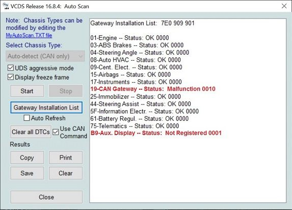
In VCDS, open Auto Scan and select Gateway Installation List. This is what you will see:

Imagen

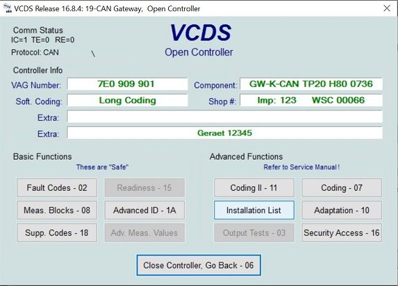
The Auxiliary Display needs to be registered and the error codes cleared. Click on "19-CAN Gateway" in the list to open that controller.

Imagen

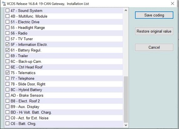
Click Installation List and scroll down the list of installed equipment, looking for "B9 - Aux. Display."

Imagen

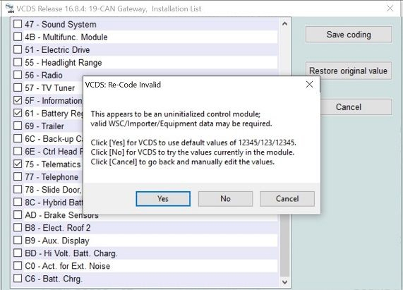
When you check the box for "B9 - Aux. Display," this message will pop up. I selected No, for VCDS to try the values currently in the module.

Imagen

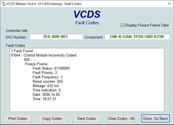
After successfully registering the Aux. Display, go back to the Controller menu and click on Fault Codes. Here is the fault you will see for the Can Gateway.

Imagen

Select Clear Codes, and click Yes to confirm. Select Go Back, Close Controller, and back out to the Auto Scan list of installed modules.
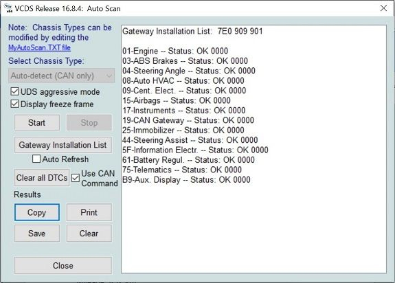
Refresh it, and it should now have the errors removed, as below.

Imagen

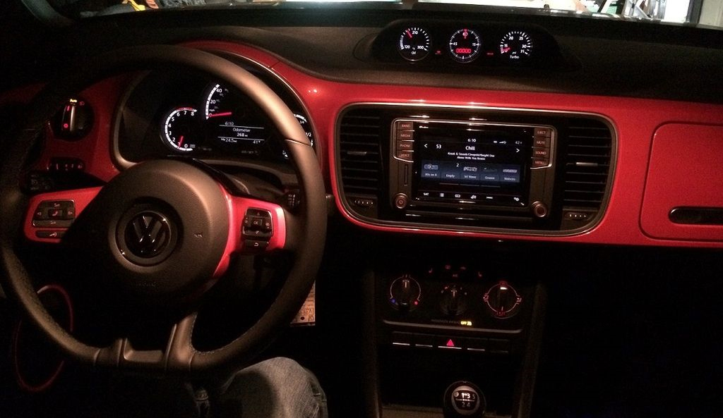
You're done! Enjoy your gauges!

Imagen

Source | VWvortex


Desconectado
 Perfil  
Mostrar mensajes previos:  Ordenar por  
Nuevo tema Responder al tema  [ 2 mensajes ] 

Todos los horarios son UTC - 4 horas


 ¿Quién está conectado?

Usuarios navegando por este Foro: No hay usuarios registrados visitando el Foro y 2 invitados


No puede abrir nuevos temas en este Foro
No puede responder a temas en este Foro
No puede editar sus mensajes en este Foro
No puede borrar sus mensajes en este Foro
No puede enviar adjuntos en este Foro

Buscar:
Saltar a: